Transonic Compressor 1

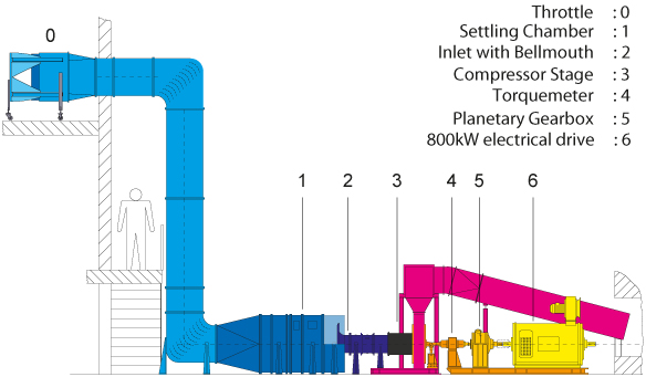
The test rig for a one stage transonic compressor is based on an open-circle concept. Air is sucked into the compressor via a throttle and a settling chamber. The massflow is measured at the calibrated inlet bellmouth. At the compressor outlet the air is guided through a throttle and a collector box and emitted to the ambience. The compressor is driven by an 800 kW electrical drive. The speed transformation from motor speed to compressor speed is achieved by a planetary gearbox. Measurement of compressor performance and efficiency is realized by a torquemeter.

Virtual Lab Tour

Configuration: 1 or 1.5 stages
Drive power: 800 kW
Outside diameter 0,38 m
Typical massflow: 16 kg/s
Typical pressure ratio: 1,5
Typical Mach Zahl (Roto relativ): 1,4
Max. Speed 21000 rpm
Conventional: Total pressure and total temperature at stage exit


3-Hole-Probe Exit-rake
Wall pressure
Unsteady wall pressure measurement (Kulites)
Measurement at stator leading edge (steady and unsteady)
Probes: 3- & 5-Hole-probe
Unsteady Probe for total pressure (Kulites)
Optical: L2F-Velocimetry
PIV
Blade-vibration: Strain-gauge measurement System
Capacitively
Rotor Tip Clearance: Capacitively
  • AG Turbo (COOREFlex-turbo, COOREFF-T, COORETEC)
  • DFG Vorhaben (FOR1066 u.a.)
  • Eigeninitiierte Vorhaben mit dem NASA Glenn Research Center
  • FP7 EU Vorhaben (FUTURE, E-BREAK)
  • Forschungsvereinigung Verbrennungskraftmaschinen (FVV)
  • Luftfahrtforschungsprogramm (LuFo)