The fan test rig at TU Darmstadt is a further development of the TSV2 with an open circuit, whereby the ambient air drawn in is preconditioned in a stabilisation chamber using wire and honeycomb grids. It passes through the inlet nozzle into the fan stage, which consists of a blisk rotor and a stator. The compressed air then passes through the support struts, the radial diffuser and the ring-shaped throttle and is released back into the environment via a collector box and an outflow duct.
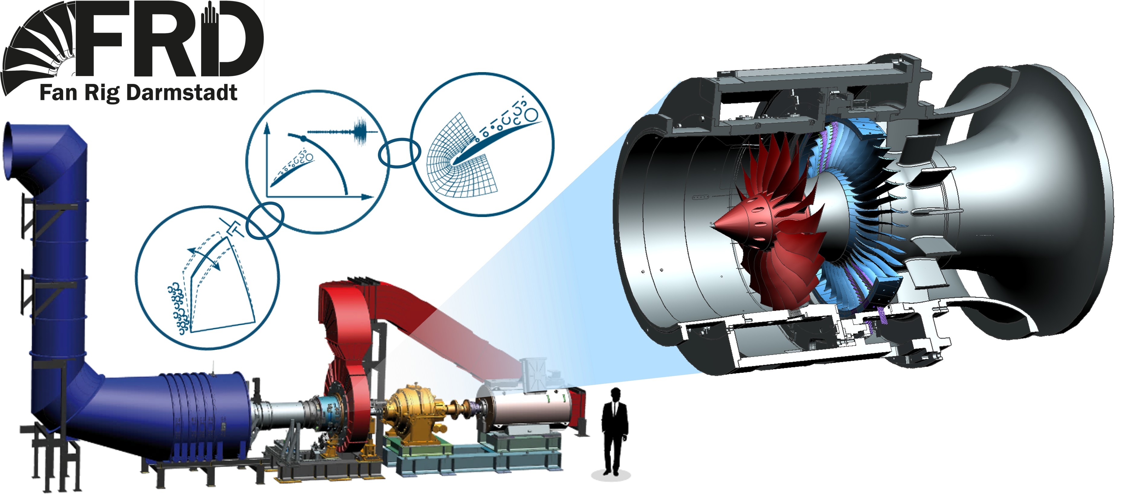
The mass flow is determined in the calibrated inlet nozzle using the differential pressure method and adjusted with the back pressure via the adjustable throttle ring. At critical operating points, the back pressure can be reduced immediately either manually or automatically via an emergency bleed. The rotor is driven by a three-phase motor via a planetary gearbox, both of which are connected to a separate cooling water and oil system. Speed and torque are recorded via a torque measuring flange. Safe operation of the system is ensured by an emergency stop logic in the control system.
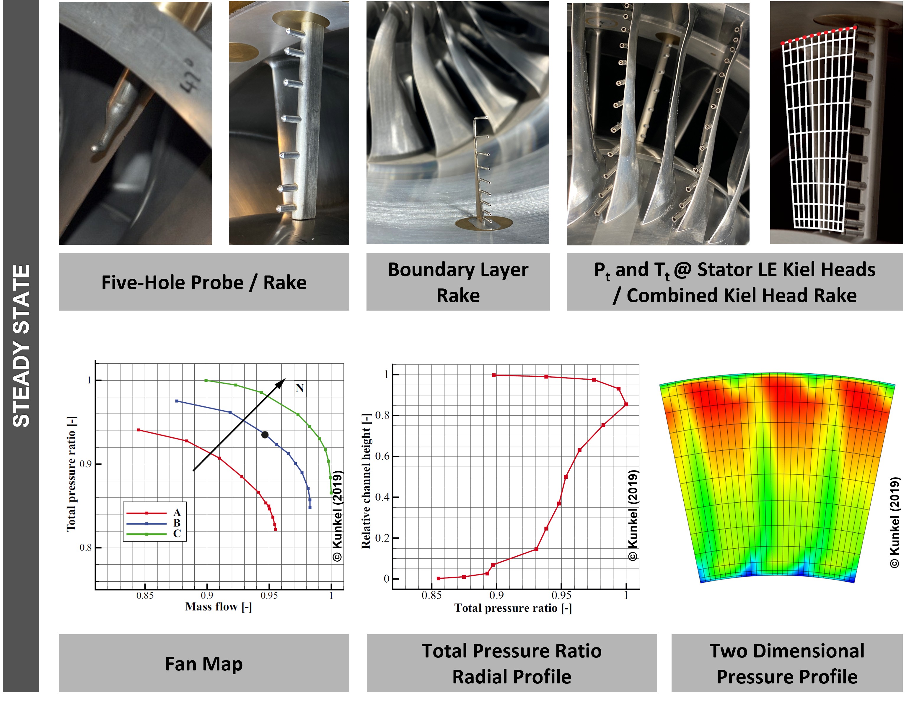
The test rig's instrumentation records data in two categories: stationary data and time-resolved, synchronised data.
Stationary parameters, e.g. wall pressure, total pressure as well as flow and metal temperatures, are recorded at approx. 100 Hz and used in the analysis to analyse constant operating points. The test rig is equipped with pressure scanners and thermocouple channels to record this data. The data is used to generate compressor maps (0D), radial profiles (1D) and flow cross-sections (2D), for example, which can be used to analyse the stationary aerodynamics of the fan stage and compare the variants or the numerical prediction. Flow angle, Mach number, static and total pressure can be resolved locally in several planes using traversable 5-hole-probes.
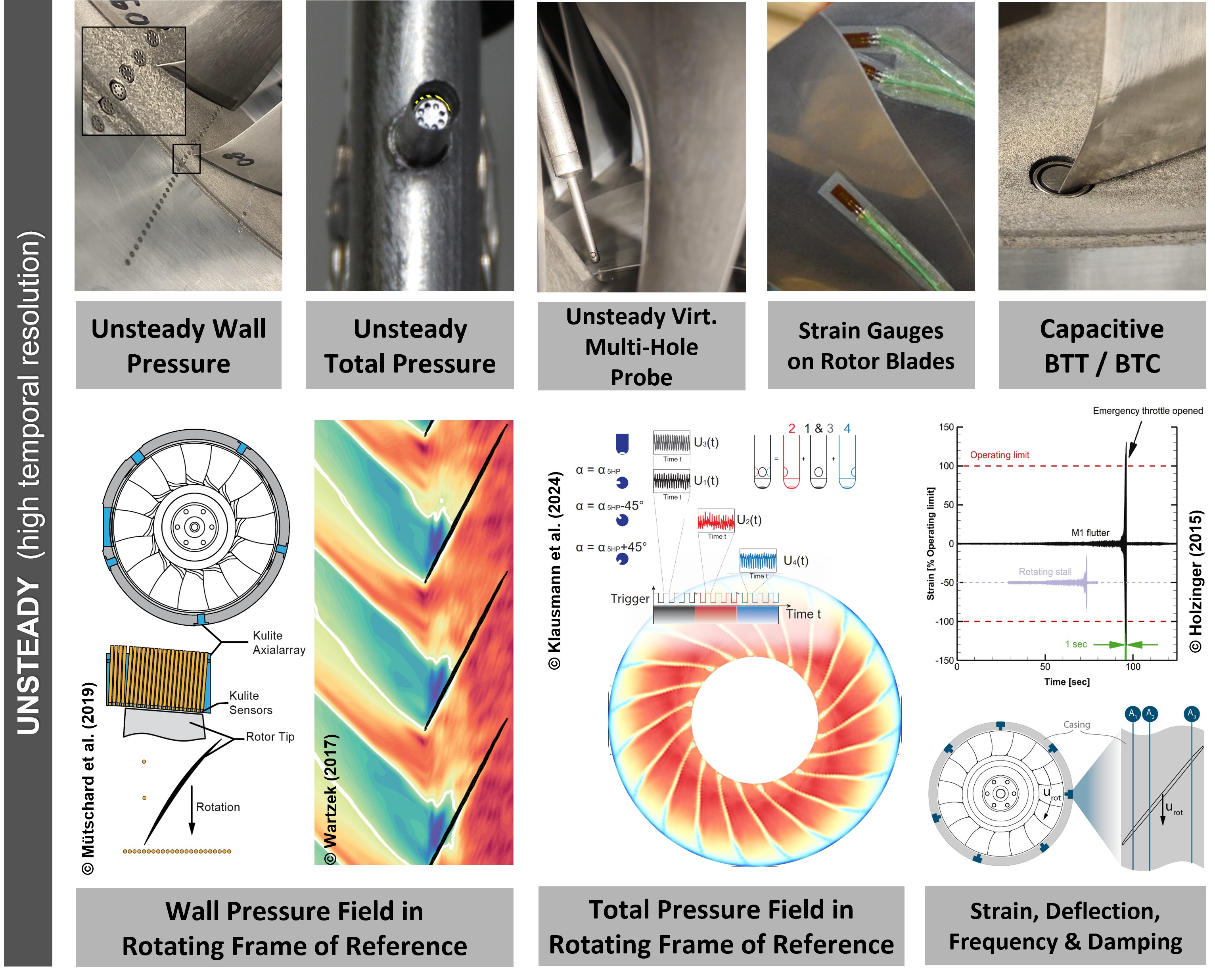
Time-resolved parameters are recorded at 100 kHz – 1.3 MHz to capture high-frequency phenomena. The multi-physical, time-synchronised recording of wall pressure, total pressure, strain, distances and vibrations is essential for aeroelastic research. For this purpose, the test rig has two transient recorders for piezoelectric pressure transducers, a measuring system for strain gauges including telemetry for signal transmission from the rotating system, a capacitive blade tip gap and running time measuring system as well as vibration and distance sensors. All time-resolved signals are provided with a unique marker (sync trigger) and can be analysed phase-accurately via this in the evaluation. This consists of automated algorithms in which the current analysis methods as well as our own specialised approaches are implemented. This is used to visualise and analyse instationary phenomena, especially near the rotor. Some examples of this are supersonic flow phenomena (shock), secondary flows, pressure and vibration spectrograms, rotational speeds, aeroelastic couplings and phase relationships, acoustic resonances and much more. In addition, traversable probes are used, e.g. virtual 4-hole-probes, total temperature probes or hot-wire probes to record flow angles, turbulence or temperature with local resolution from further processing of the data.